When building a high-performance computer or diagnosing thermal throttling, the vast majority of attention is laser-focused on the CPU and the graphics card. Users obsess over liquid coolers, massive dual-tower heatsinks, and complex fan curves to keep core temperatures in check. However, there is a hidden thermal bottleneck on every motherboard that is frequently ignored until it causes catastrophic system instability: the Voltage Regulator Module (VRM).
The VRM is the unsung hero of your PC’s power delivery system. It acts as an aggressive electrical transformer, intercepting the high-voltage power supplied by your power supply unit (PSU) and meticulously stepping it down to the exact, micro-volt requirements of your processor. This brutal electrical conversion process generates immense heat. If a motherboard’s VRM overheats, it will ruthlessly throttle your CPU to a crawl to save itself from catching fire—even if your CPU temperature is sitting at a perfectly chilled 40°C.
This comprehensive guide dissects the electrical anatomy of a motherboard VRM, explains the physics of power phases and MOSFET switching, diagnoses the hidden symptoms of VRM thermal throttling, and provides actionable cooling strategies for modern high-draw architectures.
1. The Anatomy of a VRM: How Power Delivery Works
To understand why a VRM generates lethal heat, you must understand its functional purpose. A standard PC power supply feeds 12 Volts (12V) of Direct Current to the motherboard via the 8-pin (or dual 8-pin) EPS CPU power cables located at the top-left of the board.
However, modern CPUs do not operate at 12 Volts. They operate at roughly 1.0 to 1.4 Volts. If you pushed 12V directly into an Intel Core i9 or an AMD Ryzen 9, the processor would instantly vaporize. The VRM’s job is to rapidly step that 12V down to ~1.2V while simultaneously providing massive amounts of current (often exceeding 200 to 300 Amps under heavy load).
A VRM is not a single chip; it is a complex circuit composed of four primary components working in tandem, collectively referred to as a “Power Phase.”
- The PWM Controller (The Brain): A digital micro-controller that constantly monitors the CPU’s voltage requests and sends rapid on/off signals to the VRM phases to deliver the exact required voltage at any given millisecond.
- The MOSFETs (The Heavy Lifters): The Metal-Oxide-Semiconductor Field-Effect Transistors act as high-speed electrical gates. They rapidly switch on and off thousands of times per second to chop the 12V power down to a lower voltage. This is the component that generates 95% of the heat in a VRM circuit. (Modern high-end boards combine the high-side and low-side MOSFETs into a single, efficient chip called a Power Stage or DrMOS).
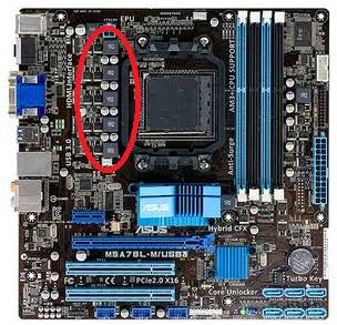
- The Chokes (Inductors): The square, gray, metallic blocks visible surrounding the CPU socket. They take the choppy, pulsed power coming from the MOSFETs and use magnetic fields to smooth it into a steady flow.
- The Capacitors: The small cylindrical cans located right next to the CPU socket. They act as the final electrical filter, storing a tiny reserve of power to ensure the voltage delivered to the CPU is perfectly flat and free of “ripple” (electrical noise).
2. The Physics of VRM Heat: Amperage and Switching Losses
The heat generated by a VRM is the direct result of electrical resistance and switching inefficiency, governed by the formula for power loss: $P = I^2 \times R$ (Power Loss = Current Squared multiplied by Resistance).
- Conduction Losses: Even the highest quality MOSFETs have a tiny amount of internal physical resistance when they are “open” and passing electricity. Because modern CPUs draw incredibly high Amperage (Current), and Current is squared in the power loss formula, even a microscopic amount of resistance results in massive thermal waste.
- Switching Losses: MOSFETs do not switch on and off instantly. There is a microsecond where they are in a state of transition. During this transition, they bleed power as pure heat. The faster the PWM controller forces the MOSFETs to switch, the smoother the power delivery, but the more heat they generate.
If you pair a high-end, 250-watt CPU (like an Intel Core i9-14900K) with a cheap budget motherboard that only has a 4-phase VRM, those four MOSFETs are forced to handle 60+ Amps of current each. The immense resistance will cause the MOSFETs to skyrocket past 110°C, leading to imminent system failure.
3. Diagnosing VRM Thermal Throttling
VRM thermal throttling is incredibly frustrating to diagnose because standard monitoring software highlights the CPU core temperature, not the motherboard VRM temperature. Users will often see their CPU sitting at a cool 65°C and assume their cooling is flawless, entirely unaware that the motherboard is burning up.
The Symptoms of VRM Overheating
- The Clock Speed Collapse: You are rendering a video or playing a heavy game. Suddenly, your CPU clock speed plummets from 5.2GHz down to its absolute base clock (e.g., 800MHz or 3.2GHz) for exactly 10 to 20 seconds, causing massive stuttering. Then it jumps back to 5.2GHz, only to collapse again two minutes later.
- PROCHOT EXT (External Processor Hot): Motherboards have their own thermal sensors near the VRMs. If the VRMs exceed their safe limit (typically between 105°C and 115°C), the motherboard sends an explicit hardware interrupt signal called PROCHOT EXT to the CPU. This signal tells the CPU: “The motherboard is melting. Force yourself to throttle immediately so you stop asking for so much power.”
How to Verify VRM Temperatures
To definitively diagnose VRM issues, you must bypass Task Manager and use robust telemetry software.
- Download and launch HWiNFO64.
- Scroll down to the section labeled with your Motherboard’s name.
- Look for a sensor labeled VRM, VR VCC, MOS, or Motherboard Temp 2/3.
- Monitor this sensor under a heavy CPU stress test (like Cinebench). If that specific temperature reading climbs steadily past 100°C and approaches 110°C right before your clock speeds collapse, you have definitively proven VRM thermal throttling.
4. The AIO Liquid Cooling Paradox: The “Dead Zone”
One of the most frequent causes of VRM overheating in modern PC builds is, ironically, the decision to upgrade to a high-end All-In-One (AIO) liquid cooler.
- The Air Cooler Advantage: When you use a traditional, massive tower air cooler on your CPU, the large 120mm or 140mm fans strapped to the heatsink sit directly above the VRM area. These fans generate massive amounts of “splash” airflow. Air violently bounces off the CPU fins and blows directly over the motherboard VRM heatsinks, actively cooling the MOSFETs.
- The Liquid Cooler Dead Zone: When you install an AIO liquid cooler, you move the cooling fans to the top or front of the case (on the radiator). The CPU socket area is suddenly left completely barren, covered only by the small pump block. Because there is no longer a large fan blowing directly over the socket, the VRM heatsinks are thrust into an aerodynamic “dead zone” with stagnant, unmoving air.
- The Result: A motherboard that ran perfectly fine with an air cooler may suddenly begin VRM thermal throttling the day you install a liquid cooler, despite the actual CPU core running much colder.
5. Architectural Solutions: Evaluating Motherboard Quality
The most effective way to prevent VRM overheating is to buy a motherboard with a power delivery system over-engineered for your processor. When researching motherboards, you must look past the RGB lighting and marketing jargon and evaluate the physical VRM specifications.
1. Phase Count (The “More is Better” Rule)
Instead of relying on 4 phases to do all the work, premium motherboards use 12, 16, or even 20+ power phases.
- By spreading the 200 Amps of current across 16 different power phases, each individual MOSFET only has to handle 12.5 Amps.
- Less current per component equals exponentially less resistance, meaning the entire VRM array stays incredibly cool even under massive load.
2. Component Quality (Power Stages)
Cheap motherboards use discrete, separate high-side and low-side MOSFETs. Premium motherboards use Smart Power Stages (SPS) or DrMOS. These combine the entire MOSFET assembly and a dedicated temperature sensor into one highly efficient silicon package, vastly reducing heat generation and switching losses. Look for boards advertising “70A” or “90A” power stages.
3. Heatsink Mass and Design
A massive VRM array is useless if the metal cooling it is poorly designed.
- The Aesthetic Trap: Many modern motherboards feature gigantic, beautiful, solid blocks of brushed aluminum covering the VRMs. While they look premium, solid blocks of metal are terrible at dissipating heat due to a severe lack of surface area.
- True Fin Arrays: The absolute best motherboard VRM heatsinks feature actual, thin aluminum fins (similar to a CPU cooler) maximizing the surface area exposed to the ambient case air.
6. Mitigation and Cooling Strategies
If you already own a system that is suffering from VRM thermal throttling, you do not necessarily need to replace the entire motherboard. There are several highly effective hardware and software mitigations.
1. Introduce Directed Airflow
If you are using an AIO liquid cooler and suffering from the “dead zone” effect, you must reintroduce active airflow over the socket.
- Install a high-quality exhaust fan on the top panel of your case, positioned as far toward the rear as possible (directly above the VRM heatsinks). This fan will act as a vacuum, violently pulling fresh air up across the motherboard components and instantly reducing VRM temps by 10°C to 15°C.
- Alternatively, purchase a small, specialized spot-cooling fan arm that allows you to mount a tiny 40mm or 60mm fan pointing directly at the VRM heatsink.
2. CPU Undervolting
As discussed in previous guides, undervolting is a miracle cure. By lowering the CPU core voltage offset by -0.050v to -0.100v, you dramatically reduce the total Amperage the CPU requests from the motherboard. By lightening the load on the MOSFETs, the VRM temperature will plummet without sacrificing any processor performance.
3. Enforce Strict Power Limits (PL1 / PL2)
Many motherboard manufacturers aggressively force their boards to ignore official Intel and AMD power limits out of the box (often called “Multi-Core Enhancement” or “ASUS Performance Enhancement”). This allows a CPU to draw 250+ watts indefinitely, which tortures a mid-range VRM.
- Enter your BIOS and disable these specific motherboard enhancement features.
- Manually enforce the official processor TDP limits (e.g., restricting the long-duration power limit to 125W or 181W). The CPU will run slightly slower in heavy rendering tasks, but the VRM temperatures will stabilize entirely, ending the severe stuttering caused by PROCHOT EXT throttling.
4. Extreme Solutions: VRM Monoblocks
For the extreme water-cooling enthusiast aiming for world-record overclocks, passive heatsinks and case fans are insufficient. The ultimate solution is a Monoblock. This is a custom-machined acrylic and copper water block designed to cover both the CPU and the entire motherboard VRM array simultaneously. Water is routed directly over the MOSFETs, keeping them chilled to ambient liquid temperatures regardless of how much voltage is pumped through the board. While highly expensive and entirely specific to exactly one motherboard model, monoblocks completely eliminate VRM thermal limits from the overclocking equation.